mercredi 21 janvier 2015

3Dpad hacking: Shaping the perception area


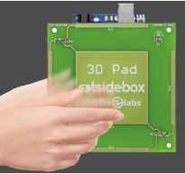
3Dpad - touchless gesture controller Arduino shield - by www.ootsidebox.com


An often asked question about 3Dpad is to know the shape of the perception area.

I'll try to answer into this page, and also I'll explain some hacks I've just done in order to shape it: smaller and bigger.
The modifications are only on the electrodes, nothing changed on the schematics, bill of material and software.
We define the perception area as a geometric zone where 3Dpad can sense the proximity of your hand or finger. The more accurate area where 3Dpad can calculate a 3D position is a little bit smaller.

The standard shape

Let's start with the standard shape, without modifying the electrodes' PCB.
Looking at the drawing below, you can see the perception area as a kind of water drop, slightly crushed on the top of the electrodes' PCB surface.


The depth perception (H) is around 10 centimeters, and there is a lateral perception (W) of around 14 centimers from the center.

A reduced shape

I made a prototype of this kind for an application where there is not enough place to put the 90x90mm electrodes' PCB. In this future product, we have the possibility of only 40x40 millimeters for the whole system, and there is a LED (square) at the center. Here is the plan of the electrodes' PCB that I used for the experiment:


There is a grounded copper around the perception area, so the sensing lateral distance is reduced. 
Here is the result:


Augmenting the perception area

I made it in the simplest way,extending the electrodes's dimension by using copper wire, directly soldered on the PCB:

This is what the new interaction area looks like now:


As you can imagine, the sensing area is also increased at the back side now, because the electrodes' extention is made of wire "in the air", sorry I didn't measure it for now.

Well, in this configuration it makes me think about a new kind of Theremin, augmented with a third dimension on each sensing plate (a Theremin has two antenna: one for the pitch and the other for volume control). In more I guess it will be easy to continue increasing the geometry, there should be only small changes on some resistor values, and software adjustment.

See it in action:


Jean Noël - www.ootsidebox.com


See also: 

lundi 17 novembre 2014

3Dpad datasheet

DATASHEET


3Dpad - touchless gesture controller Arduino shield - by www.ootsidebox.com


Mechanical dimensions:


Weight:

  • 61 gram (3Dpad shield only)
  • 90 gram (including Arduino UNO board)
Supply voltage: 

  • 12 Vdc (max 18Vdc)
Power consumption: 
  • 3Dpad shield only: 180 milli Watts 
  • Iincluding Arduino UNO board: 720 milli Watts 


See also: 

mardi 28 octobre 2014

Be aware of the Fake[Ar]duino UNO

Let me tell you the bad adventure I lived few weeks ago:
I ordered 5 Arduino UNO boards, in order to use it with a 3Dpad shield. I made this acquisition on a well known shop on the web.

But once I tried to use it with the 3Dpad, it didn't work correctly: the signal was absolutly instable. When trying to understand the problem, I saw that the system works well when the USB was unplugged, but not when it was plugged.
From that point I tried to find informations on the web, also I compared with attention this UNO board with the previous used succesfully.

And then I had the bad surprise to understand that this "Arduino" UNO board was a fake!
In more, this counterfeit is not well done and they made mistakes when copying the original.


One can see small mistakes made on the copy in the picture below:


After signaling the problem to the provider's website, I decided to see if a work around was possible, in order to make it work with 3Dpad. I made few experiments, and with the help of chance [I didnt have the fake's schematics in hand...], I discovered that cutting a wire enables the 3Dpad to work

The small modification is shown in the image below: 


Unfortunatly, I do not have a complete explaination, but I know that this trace is in relation with the USB grounding...
With this modification, your "fake" UNO USB will be recognized by the PC only when the power comes from an external supply, that fits well with 3Dpad (12V DC).


Hope this will help,

Jean Noël - ootsidebox


Find out more about the Fake Arduino UNO:


  • http://arduino.cc/en/Products/Counterfeit
  • http://makerflux.com/basic-essentials-for-spotting-a-fake-arduino/

  • http://www.massimobanzi.com


  • Find out more about 3Dpad:

    vendredi 19 septembre 2014

    Looking deeper in 3Dpad's Hardware


    Vue of the PCB and components 


    See also: 

    3Dpad Getting started guide


    In this page we will guide you to setup and use 3Dpad

    Warning: you're supposed to be already familiar with the Arduino IDE and the Arduino Uno board.
    If not it's highly recommended for you to follow a first tutorial.
    See this one for instance: http://arduino.cc/en/Guide/HomePage

    If you have any question, or need any support, feel free to ask:


    What you'll need:


    * Please avoid poor quality switching supply, they are often to noisy for 3Dpad.
    * Our recommandation:  LD137 -  XCSOURCE


    Setting up the hardware

    Plug the 3Dpad shield on the Arduino Uno board, be carefull to align the connector as shown below:


    Plug the power supply and the USB cable to the UNO board


    Setting up the Arduino software

    3Dpad's Arduino Sketch and librairie:

    Download the latest version on GitHub:


    You can now compile, download and run the 3Dpad's sketch.

    For the next step, enter in communication with the UNO board using your favorite terminal software (you can also use the one provided by the Arduino IDE).
    You should use a speed of 115200 bauds.

    As this is the first time that 3Dpad is running, you will obtain this on the terminal:


    The calibration process is working, and you have to wait few seconds to the end (maximum 30 seconds) .... avoid to put anything in front of 3Dpad at the moment.
    At the end of the process, you should see:


    Bravo! your 3Dpad is now operationnal. 

    The LED at the bottom left corner must be lit. Now approach your hand in the front of the electrode PCB,
    at level below 10 centimeters, the LED at the bottom left corner must become off and the LED at the top right corner becomes lit.
    This indicates that you are inside the detection area.

    In more, you should see the results of the gesture recognition on the terminal, for instance:


    Use the terminal for sending orders and for visualizing 3D coordinates

    As suggested at the top of the terminal window, you can send orders to the 3Dpad, the commands are trigged when you'll send a character:

    'A' => will start an autocalibration process:
    3Dpad will search the best tuning of the sensor, and store the values in the EEprom.
    It can take up to 30 seconds.

    'S' => the command for a "Setup": 
    The sensor starts using the values previously stored in the EEprom, and quickly search for the current tuning values.
    This takes less than 2 seconds.

    'G' => you'll have only the gesture recognition results sent to the terminal

    'V' => the terminal will recieve a row data, with all the calculated values, including 3D coordinates.


    Detail of the row data:
    The line starts with a prompt '>' just followed by 'V', which indicates that this line contains values (instead of 'G' for gestures and 'A' for the internal automata state).

    Then come the values, coded on 4 digits and separated with the '|' character.

    The values are, from first to last:
    1. Top electrode activation
    2. Bottom electrode activation
    3. Left electrode activation
    4. Right electrode activation
    5. X position coordinate (the estimated position of hand/finger)
    6. Y position coordinate
    7. Z position coordinate
    8. X dynamic origin position (internal use for gesture recognition)
    9. Y dynamic origin position (internal use for gesture recognition)
    10. Z dynamic origin position (internal use for gesture recognition)
    11. Turn counting (clockwise)
    12. Turn counting (anti-clockwise)
    Now that you know everything, you are free to use 3Dpad into your own application.
    Also you should be interested in the 3Dpad's demo software, just follow the links: 

    3Dpad's demo software - Processing

    Also you may be interested in: